
Texto Industrial Air Conditioning & Unit Heaters | Updated: July 31, 2026
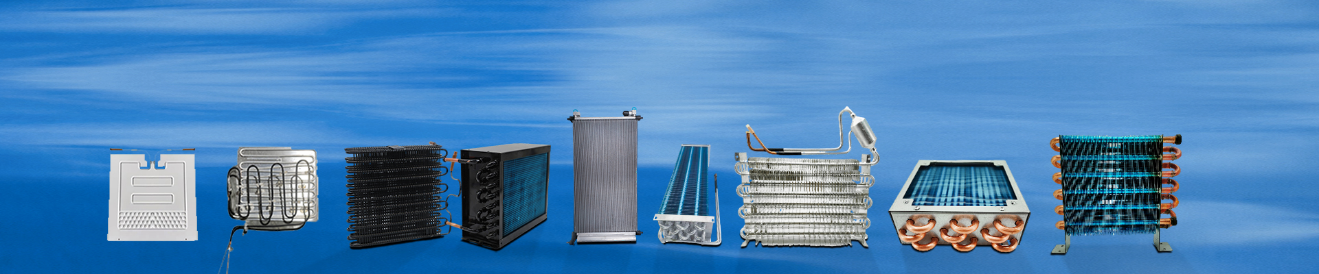
As a critical heat exchanger in refrigeration systems, the fin condenser’s core function is to rapidly transfer heat from high-temperature, high-pressure refrigerant vapor inside tubes to ambient air, so that the refrigerant condenses into liquid. To achieve efficient heat exchange, its structural design consists of five core components as detailed below:
1. Core Heat Transfer Components: Condenser Tubes & Cooling Fins
Heat Transfer Condenser Tubes
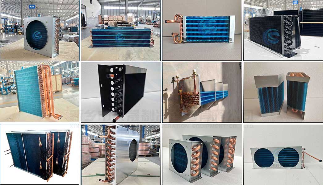
Used as internal flow channels, condenser tubes are generally manufactured from copper or aluminum with superior thermal conductivity. To extend the contact duration between refrigerant and tube walls within limited space, tubes are bent into regular serpentine S-shapes or folded into cubic structures via bending machines.
Heat Dissipation Fins
Air features a low heat transfer coefficient. Dense fins are mounted outside condenser tubes to expand heat exchange area and boost air turbulence. Fins are commonly made of high-purity industrial aluminum and available in flat, corrugated and wave styles. Precisely sized mounting holes with flanged edges are reserved on each fin to maximize contact area with condenser tubes.
2. Assembly & Fastening Structure
Fin Sleeving & Tube Expanding
Aluminum fins are arranged in equal linear spacing and sleeved onto condenser tubes. A mechanical tube expanding process deforms copper tubes plastically to create tight contact between tubes and fins, eliminating contact thermal resistance.
Fixing Brackets
Custom metal support brackets are equipped to prevent fin bending and displacement. Clamped firmly onto tube surfaces, the brackets maintain uniform tube spacing and protect fragile fins from external mechanical damage.
3. Fluid Distribution Assembly: Headers & Manifolds
Header Pipes
Installed on both ends of the condenser, headers evenly distribute and collect refrigerant. For parallel-flow condensers, internal partition baffles inside headers guide refrigerant to flow through flat tubes along designated routes.
Manifold Tanks
Both ends of finned tubes are welded or expanded onto manifold tanks. Multiple tank types are applied according to working pressure: flange-type for medium-low pressure systems, plug-type and header-integrated tanks for high-pressure applications. To accommodate thermal expansion and contraction, one manifold tank is designed for free displacement along the tube length.
4. Auxiliary & Enclosure Structure
Outer Shell & Cavity
Some condensers adopt hollow multi-cavity shells with bundled internal copper tubes to reduce overall dimensions, supporting compact equipment design. Extra parallel outer cooling fins are added on the shell exterior for enlarged heat dissipation capacity.
Ventilation Matching System
As an air-cooled heat exchanger, the fin condenser works with axial fans and fan brackets to force airflow through fin surfaces and carry away waste heat efficiently.
5. Special Functional Accessories
Receiver Dryer
Many parallel-flow condensers integrate a built-in dryer on one side of the header pipe. Filled with desiccant, the dryer absorbs moisture and impurities inside refrigeration circuits to guarantee stable long-term system operation.