
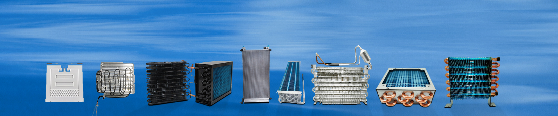
Working Principle of Evaporative Cooling Condenser
An evaporative cooling condenser uses water and air as cooling media, utilizing the evaporation of water to remove the condensation heat of the refrigerant.
During operation, cooling water is delivered by a pump to spray nozzles located at the top of the condenser tube bundle. The water is evenly distributed over the outer surface of the condenser plate tubes, forming a thin and uniform water film. High-temperature gaseous refrigerant enters the condenser from the upper section of the tube bundle. As heat is absorbed by the cooling water on the outer surface of the tubes, the refrigerant condenses into liquid and flows out from the bottom.
Part of the cooling water evaporates into water vapor after absorbing heat, while the remaining water flows into the water collection basin at the bottom of the condenser and is recirculated by the pump. A fan installed at the top of the condenser forces air to flow across the condenser tubes at a velocity of approximately 3–5 m/s, promoting rapid evaporation of the water film and enhancing heat rejection from the condenser tubes. The airflow also cools the falling water droplets, allowing water vapor to be discharged with the air stream. Unevaporated water droplets are captured by a drift eliminator and returned to the water basin. A float valve is installed to automatically control the makeup water supply.

Climatic Conditions for Evaporative Cooling Condenser Applications
In theory, the lowest achievable air temperature in direct evaporative cooling is the wet-bulb temperature, while in indirect evaporative cooling, it is the dew point temperature. Based on the operating principle of evaporative cooling condensers, the greater the difference between the dry-bulb temperature and wet-bulb temperature, the better the evaporative cooling performance.
In dry and arid regions, especially in northern climates, evaporative cooling condensers can achieve significantly higher heat transfer efficiency, making them an ideal solution for energy-efficient refrigeration systems.
Comparison Between Evaporative Cooling Condensers and Centralized Water-Cooled Systems
When upgrading existing air-cooled HVAC systems in data centers or critical equipment rooms, factors such as system safety, operational stability, heat transfer efficiency, installation complexity, footprint, flexibility, and future expansion must be carefully evaluated.
Compared with centralized water-cooled systems, evaporative cooling condensers demonstrate clear advantages in terms of condensing method, lower condensing temperature, simplified retrofit requirements, reduced engineering workload, smaller installation area, lower system complexity, greater flexibility, higher operational reliability, and improved system safety.

Advantages of Evaporative Cooling Condenser Systems
Evaporative cooling condenser–based HVAC systems offer the following key benefits:
1. High Cooling Capacity and Low Energy Consumption
Under identical ambient conditions, the condensing temperature of an evaporative cooling system is 5–8°C lower than air-cooled systems and 2–5°C lower than conventional water-cooled systems. This increases the refrigeration capacity per unit mass flow of refrigerant, reduces compressor operating time, and significantly lowers energy consumption. Studies indicate that evaporative cooling systems can achieve approximately 30% energy savings compared with air-cooled systems.
2. Low Maintenance Cost
Modern evaporative cooling condensers are manufactured using corrosion-resistant, high-thermal-conductivity metal plate tubes and employ high-efficiency flat liquid film heat transfer technology. These features make cleaning and maintenance simple while ensuring long-term stable heat transfer performance.
3. Advanced and Intelligent Control
Evaporative cooling condenser systems utilize intelligent control technology with a high level of automation. Features include coordinated control between the condenser and indoor units, optimized start-stop management, comprehensive fault alarms, self-diagnostic functions, and water shortage protection. These capabilities ensure energy-efficient, safe, and reliable operation.
Unsaturated Cooling Condenser
Heat and Mass Transfer Mechanism
The cooling section and condensation section are defined based on the dew point of the condensable component in the gas mixture. From the gas inlet to the point where the gas temperature reaches the dew point is referred to as the cooling section, while the region from the dew point to the gas outlet is the condensation section.
In the cooling section, the unsaturated gas mixture—composed of non-condensable gas and condensable vapor—does not experience a change in composition, as the condensable vapor has not yet reached saturation. Heat transfer occurs solely through the gas boundary layer to the heat transfer surface of the tubes.
Equipment Design Methodology
The primary objective of equipment design is to determine structural parameters and perform heat and mass transfer calculations based on process requirements. These calculations reflect the internal heat and mass transfer behavior of the condenser and guide necessary structural optimization to achieve high thermal efficiency.
The design process typically follows these steps:
-
Calculate the gas dew point using phase equilibrium based on the partial pressure of the condensable vapor at the gas inlet.
-
Divide the process into stages: cooling section (from inlet temperature to dew point) and condensation section (from dew point to outlet). The condensation section is further divided into 3–7 calculation zones to ensure accuracy.
-
Assume gas pressure at each temperature point and estimate the total pressure drop (HP) from inlet to outlet.
-
Perform heat and material balance calculations for each zone, determining heat release, gas flow rates, condensed vapor flow, and cooling water temperature.
-
Calculate the number of heat transfer units for each zone.
-
Estimate the required heat transfer area.
-
Conduct mechanical design based on the estimated heat transfer area, including tube specification, material selection, tube bundle layout, shell diameter, and baffle arrangement.
-
Calculate shell-side average heat transfer coefficients and flow pressure drop.
-
Finalize structural parameters when all design criteria are satisfied:
-
Estimated heat transfer area meets or exceeds required area;
-
Difference between assumed pressure drop (HP) and calculated pressure drop (Px) is within allowable tolerance;
-
Heat transfer area is minimized within process constraints.
-
-
Adjust structural parameters and repeat calculations if requirements are not met until all design criteria are fulfilled.
Due to variations in gas properties and equipment configurations, appropriate heat and mass transfer correlations should be selected according to specific operating conditions.